No-Can-Dew telescope dew buster

The design criteria was simple - a 12V adjustable heating system that could heat my corrector plate enough to keep it dew free. Also, I wanted several controls in one unit, since I also wanted to heat my finderscope, my eyepiece, and my Telrad finder. Simple enough.
My research led me to some pages about soldering multiple resistors together to supply heat around the optical tube - something I plan on doing for my finderscope and my eyepieces, but around 37" circumference optical tube!!?? I wanted to be dew free THIS year. Then I found Mark's pages about using nichrome wire as a heating element - it's simple and it doesn't look like it got hit too many times with the old ugly stick.

schematic diagram
I also contemplated using a PIC microcontroller - which I may still do in a future project. In the end, I opted for (2) 556 dual timers, with power MOSFET outputs. To the left is the schematic I came up with (click it for a larger view).
The 556 is a dual timer, set up in astable mode, meaning that it's essentially generating two independent pulse width modulated square waves, ad-infinitum. My controller has TWO of the circuits shown in the schematic - to give a total of FOUR independent control channels. Note that you CAN run multiple lower power heaters from a single channel - i.e. - eyepiece, finder, and telrad heaters could be run in parallel off a single channel, sacrificing independent temperature control for each - and thus you would need only ONE circuit board module (one channel serving the "main" corrector plate heater and the other serving the combined other smaller heaters).
The period of each channel is just over one second, which seems to work well, AND gives the option of adding a "status" LED for each channel (in parallel with each heater) to give a visual indication of its duty cycle. The key is not to overpower the heating process - but to keep it just at the point where you need it - thereby preserving battery life, minimizing thermal layering and air currents, and keeping your viewing at optimum quality.
The choices for driving the output were either relays, power transistors, or power MOSFETs. Relays were too noisy and their mechanical nature may spell difficulties down the road for a constant cycling application such as this. Power transistors are not energy efficient enough (they get hot and need a heat sink - wasting heat and power where you don't need it). Power MOSFETs, if chosen properly, can do the trick nicely, with very little power wasted (and no heatsink). Keep in mind that MOSFETS are sensitive to static discharge, so you should wear a ground strap while handling them and assembling this circuit!


foil side vs component side

ready to etch
Here's a picture of the board with the rub-down transfers in place,
ready to be etched.

the board after etching
Note that the boards were not identical - I experimented a bit with layout - although the circuits are the same, I used slightly different pads and paths.

the case, ready to be assembled
Assembly was straight forward - the MOSFETs were installed back-to-back but NOT touching (this is critically important). I drilled the holes in the case for the pots, switches, and jacks, after figuring on clearance from hot-gluing the circuit boards to the bottom of the case. My first choice for MOSFETs were el-cheapo IRF510's - however, these got too hot for the BIG heater, so I had to change the MAIN heater controller MOSFET to a IRFZ34N, which was about twice the price.
- for Rh = 8ohms to 24ohms, use IRFZ34N
- for Rh > 24ohms, IRF510 will suffice (this was previously listed for 8-100 ohms, but the IRF510 will handle a 24 ohm heater with a power dissipation of only 0.135W)
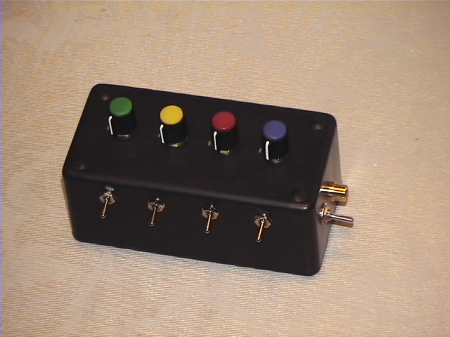
front view

rear view
- You'll notice that there are NO LEDs on it - this is for three reasons:
- they're not needed for it to function
- the pots give you some idea as to the duty cycle percentage
- I would have had to add another switch so I didn't have to see distracting winky lights all the time (could have been done on the "empty" end of the case, and I might add it sometime)

nichrome wire
Thus R = 144/15 = 9.6 ohms . . . I needed to create a 9.6 ohm heating element out of nichrome. Now, I also wanted to go around the telescope tube a fixed number of times - not 1.25 turns, not 3.6 turns. Upon measuring my scope circumference, it was 37", or 3.08 feet. So I had to find a nichrome wire with a characteristic resistance such that one, two, or three loops of 3.08 feet would provide just over 9 ohms of total resistance. I thought that to heat evenly and "gently", two loops would be better than one, since it would transfer the heat over a larger surface area and reduce the "point" wire temperature. As it turns out, this was a good idea, since part of the wire is not in contact with a good thermal conductor.
The nichrome I used was from Lile Engineering, who offer it at a very reasonable cost and were very helpful with suggestions on end point terminations. In the end, I opted to use nichrome with a characteristic resistance of 1.47ohms/ft - which resulted in a total resistance (Rh) of 9.06ohms. Bingo. Close enough for me. Here's a picture of the wire, and Lile Engineering's part#.
The 9.06 Ohm length results in a current of 1.32A, and a heating power of 15.8W.

first strip of double-sided tape

first strip in place

both strips of tape, backing removed
My wife made a brilliant suggestion, of using double-sided sticky tape that's normally used for insulating windows with plastic in these cold Canadian winters. Since I had 2 loops of wire to make, I used 2 "runs" of this tape beside each other.
Then I tucked the nichrome wire conveniently into a little ridge in the corrector plate housing, looped it once, crossed it over the center line, and looped it again tucked in the opposite ridge. I left about 6" of spare on both ends, so I could terminate on a terminal strip.
Before I could terminate it on the screw terminals, I had to somehow bring the LEFT side end out across the other conductor - so I cut a small square of a plastic food container and drilled two holes in it to act as an insulator, and ran both end wires UP through the holes, and over to the terminal block.
I ran it through both sides of the terminal strip, under BOTH screw terminals, and connected solder-tinned wires (to the plug) under ONE side's screw terminals. I then tightened the screws VERY well to minimize resistance of the connection.


wire crossover & closeup

white duct tape to protect the heater
and the final product!