Simcoe Skies Astronomy
**** 12-minute Drift Alignment Recipe
****
REVISED JUNE 28/09
Important Note: I discovered an error in my procedure regarding compensation factors for stars with different DECLINATIONS -
there IS no compensation factor, as the DEC drift rate is NOT impacted by the declination of the target. This
was corrected on June 28/09.
Drift alignment can be a long and painstaking process, but it's necessary
for astrophotography. After an initial 30-minute measuring session, this method will have you accurately drift aligned in just over 10 minutes!
What is Drift Alignment?
Drift alignment is normally a slow process. You measure drift over time, try to adjust your mount to compensate, remeasure drift,
readjust, etc. until you have very little drift. It's necessary to tweak both axes separately, so it's 2x the work
that one might originally think. Drift alignment has taken me hours, or multiple nights to perform. During an off-site
outing, this isn't an option. This method however, makes it viable and even simple!
Principle & Theory
By identifying the rate of drift per unit of axis offset and having an accurate method to measure this offset, you can drift
align by one simple correction on each axis.
Initial Requirements
You need to prepare 2 items prior to the first time you do this. You can re-use these every time you
drift align (either at a new site or if your mount position has changed), so it's an investment with return!
Here's what you need to use:
- a $2 laser pointer
- some steel-reinforced epoxy
- a darkened photocopy (or one with black lines) of an 8½ x 11 sheet of graph paper (1/4" quadruled works well)
- a clear plastic "protector sleeve" or laminator for the graph paper
- a piece of plywood or aspenite a little larger than the graph paper
- a small L-bracket and a ¼:20 nut (or drill/tap a hole in the bracket to ¼:20
- a couple of short screws (to fasten the L-bracket to the plywood)
- four tacks (to pin the graph paper to the plywood)
- a camera tripod
- 2 strips of black electrical tape, 1-2" long (fold the end over a tad so it's easy to remove)
- a fine-tipped dry-erase/whiteboard marker
- K3CCDtools for drift explorer function
- A piece of string to keep future target setups at the same distance from your mount
One-time preparation:
- Epoxy a $2 laser pointer to the mount (it should move around as you
adjust the alt/az but not when you move RA/DEC).
Note: it's best to select an orientation for the laser that would normally
project the beam onto a stationary surface like a wall, fence, tree if you often set up at the same location.
---For a good example of an installation, see Mike Gray's page here.
Note: You MAY be able to temporarily attach (via electrical tape wrapped around it and the mount, for example) a collimating
laser to your mount for a less-permanent solution.
- Take a piece of 8½ x 11 graph paper (¼" quadruled) and photocopy it so the lines
are black.
- Either laminate the graph paper or put it in a plastic protector sleeve
- Screw the L-bracket to the backside of the plywood near the bottom (landscape orientation) so it can
be fixed to the camera tripod with the ¼:20 nut.
- Pin the laminated/sleeved graph paper onto your plywood (again, landscape orientation)
Now for the procedure...
 |
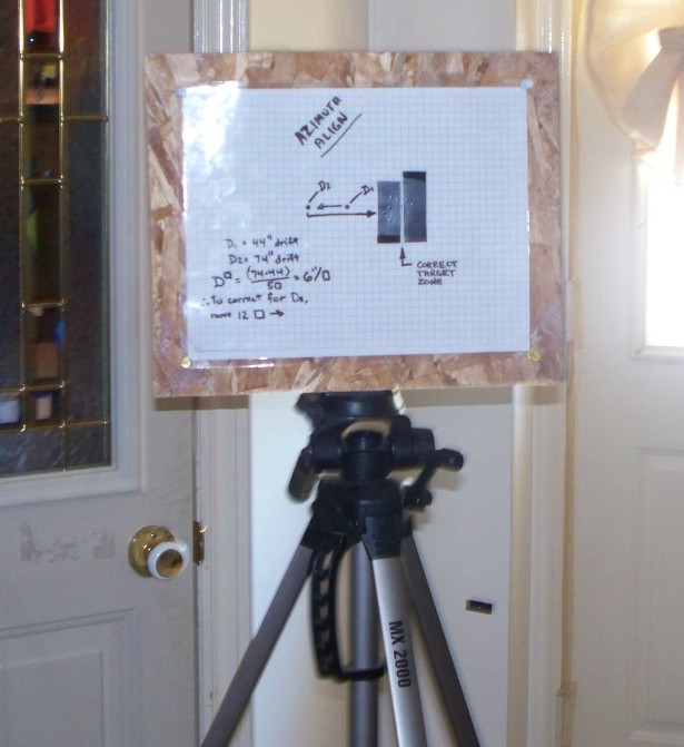
Set up the graph paper target on the tripod so the laser hits it somewhere around
the middle of the paper (preferably on a line/line intersection)
(somewhere around 10 feet from the mount is fine).
Using the drift explorer function of K3CCDtools, track a southern
star on the meridian for 5 minutes with your camera, and write down the accumulated DEC
drift (**unless your RA axis is horizontal on the screen, you may want to perform drift explorer's angle calculation function first while turning off your tracking).
Move the mount so that the laser beam hits the graph paper FIVE
SQUARES (5 instead of 1 increases the overall accuracy, but this has nothing to do with the 5-minute drift
period) to the left of
where it did previously, and redo the 5-minute session, noting the NEW
DEC drift.
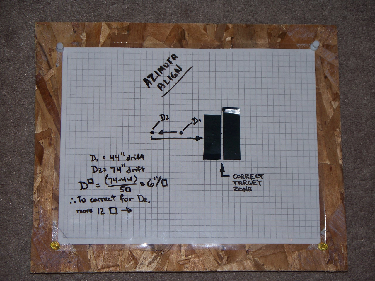
The difference between the 2 results, divided by 5 is your "DEC
DRIFT PER SQUARE" - WRITE THIS DOWN FOR FUTURE USE. Calculate how many squares are needed to compensate
for the total DEC drift noted during the last 5-minute session, and
move the mount accordingly. Azimuth alignment complete!
Repeat the process with a star low in the east or west, for altitude
(latitude) adjustment (obviously you move the beam VERTICALLY instead). AGAIN, WRITE THIS DOWN
FOR FUTURE USE - NOTE IT'S FOR THE ALTITUDE ALIGNMENT AND WILL LIKELY BE DIFFERENT.
Now, before you pack things up, get a roll of string, and cut a piece about two feet longer than the
distance between your mount and your "target" tripod. Tie a slip-knot on one end, and loop it around your mount.
Gently extend the string out to your "target" tripod location, and cut it to length so it just touches the graph paper.
By using this same distance between your mount ant the tripod EACH TIME, the DRIFT PER SQUARE (DPS) in each axis will
remain CONSTANT!
|
FUTURE drift alignments at any location (using the string for correct distance) will take just over
10 minutes, since you'll only have to measure drift on each axis ONE TIME (provided you've recorded the DPS values).
Additional Notes:
If you use PHD guiding (freeware), then you can guide in RA (only) for the period before you take your DEC
drift measurement. This will compensate for any error introduced by worm gear irregularity (periodic error),
giving higher accuracy!
I found it easiest to mark the laser starting points with a fine point
dry-erase (whiteboard) marker. Then to make things easier, make a
vertical or horizontal "white line" on the laminated graph paper where
you want to MOVE the beam to, with a strip of black
electrical tape.
For example, if you're moving over ONE square to the left, put the black tape strip
vertically on the laminated target, immediately to the right of the point where you want to move the beam to.
This creates a reflective white vertical "target zone" that's
very easy to see when you get there, regardless of distance to the
tripod/graph paper.
Also, once you've got your axis alignment for your camera sorted out (rotation), MARK some line-up matching points
on your camera and drawtube/ep holder so you don't need to do this each time. You'll need to do the same with your OTA and
its rings if it can be rotated. This is a SIGNIFICANT time-saver.
For higher accuracy, move the target/tripod further away during the process (don't forget to redefine your DPS values).
Back to Tutorials | Home